
-
09-01-2017 #1

 Last Activity: 16-08-2023


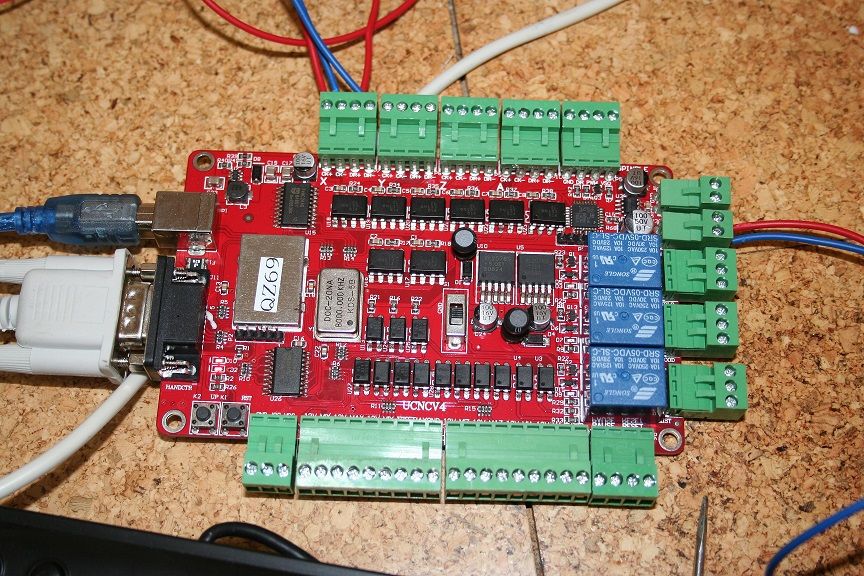
Hi, I purchased one of the cnc stepper motor kits off ebay. but the instructions are in Chinese. the only makings on the board are UCNEV4 this is the USB breakout board that also comes with the handheld pendant and power supplied. Now I am thick when it comes to electrical matters and after watching various u tube videos in which the background music overrides any voice ( what the hell is it about having music playing all the time ) anyway I watched countless videos and got know information from any of them.
so if anyone out there as also purchased one of these kits from Germany and got it all to work. could you please let me know how you wired it together a diagram if possible would be good. how are the little trips set on the stepper motor driver. here are some pics of the board and motor drivers etc
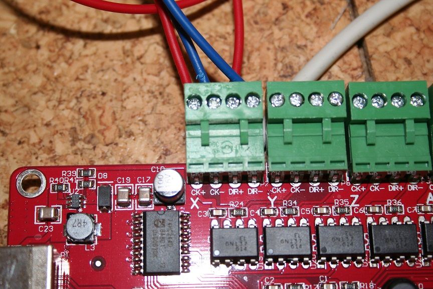
I have LED lights on the BOB but nothing at the motor driver
what am I doing wrong, and also how do you find the ports and pins for this card to use in mach3.
thanks. michael
-
09-01-2017 #2
 Last Activity: 24-07-2022


DO you have the motor power supply connected to the drives?
Gerry
______________________________________________
UCCNC 2022 Screenset
Mach3 2010 Screenset
JointCAM - CAM for Woodworking Joints
-
09-01-2017 #3
Last Activity: 16-08-2023
hi, what do you mean. the wiring goes from the breakout board to the motor driver and then from the driver to the motor. what motor power supply is there needed and how does that wire into the system. michael
-
09-01-2017 #4
Last Activity: 24-07-2022
The drives should be powered by a separate DC power supply, typically around 48V or so. I'd need to see your drives or get a model # for more info.
Gerry
______________________________________________
UCCNC 2022 Screenset
Mach3 2010 Screenset
JointCAM - CAM for Woodworking Joints
-
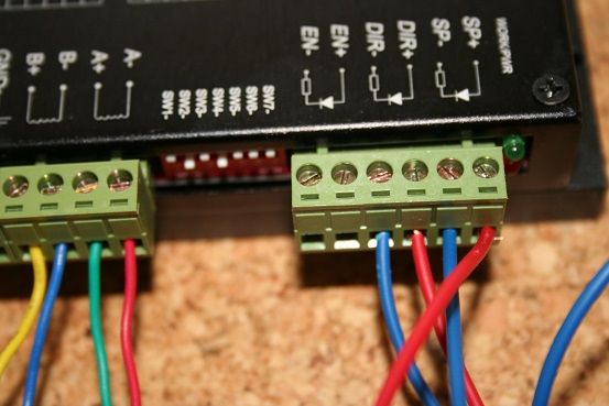
Terry if you look on the 4th pic. driver out of shot on the left hand side is where the motor power goes to. there are two terminals next to the yellow wire
 Originally Posted by terry1956

Last edited by Clive S; 09-01-2017 at 04:02 PM.
..Clive
The more you know, The better you know, How little you know
-
09-01-2017 #6
Last Activity: 16-08-2023
thanks Clive, what voltage for the driver, and do I still need a separate 5 volt input to the breakout board, or will the usb be ok.
-
I cannot guess the voltage what does it say on the driver or the model number at least Originally Posted by terry1956
..Clive
The more you know, The better you know, How little you know
-
09-01-2017 #8
Last Activity: 16-08-2023
hi, the microstep driver is a FMD2740C . apart from adding a power supply to it is there any other wiring that needs to be put in place. also how do you find the pin numbers from the card. thanks
-
Ok they are 50V drives so you will need about 36 - 45 volt DC power supply. Originally Posted by terry1956
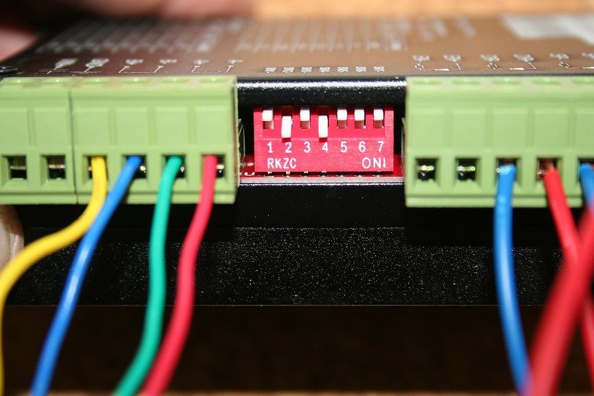
Also the dip switches you have them set at 0.5A which is far to low.. So set sw5 to on sw6 to off sw7 to on that will give you about 3 A
Are you using mach3 or what?
Edit I see it runs off usbcnc so I think this is the manual http://www.variometrum.com/PDF/USBCNC_csatolo_ENG.pdfLast edited by Clive S; 09-01-2017 at 06:03 PM. Reason: added text
..Clive
The more you know, The better you know, How little you know
-
09-01-2017 #10
Last Activity: 16-08-2023
Hi.on the motor driver there is a power in marked V+ which matches a terminal on the 36v power supply which came with the kit.however the second driver inlet is marked G for ground.the only G terminal on the power supply is on the inlet 240v side.the only free terminal is marked V-. So do I wire the driver G terminal to the G terminal on the power supply or to the free V- terminal. There are two leads on the driver,I take it the green one is power ok and the red one bad news.


 Reply With Quote


Thread Information
Users Browsing this Thread
There are currently 2 users browsing this thread. (0 members and 2 guests)
Similar Threads
-
anyone using an e-cut 1 mhz usb breakout board
By nobby in forum Control Hardware & SystemsReplies: 10Last Post: 22-10-2018, 11:50 PM -
help needed with breakout board
By terry1956 in forum Motor Drivers & ControllersReplies: 22Last Post: 07-09-2016, 07:58 PM -
Breakout Board
By Tomnewry in forum General ElectronicsReplies: 2Last Post: 12-12-2013, 07:24 PM -
FOR SALE: PMDX-122 Breakout board
By IN-WondeR in forum Items For SaleReplies: 0Last Post: 14-12-2011, 04:05 PM -
Breakout Board
By croy in forum Electronic Project BuildingReplies: 10Last Post: 18-08-2011, 07:50 AM

Bookmarks